Build your own 1530 to C16, C116 & Plus/4 adapter and make an C64 SD2IEC work on your 264 computer
on Tue Feb 21 2017 by Ingo HinterdingWhen released, the Commodore 264 series suffered from some questionable decisions regarding it's joystick and datasette ports. In this article I show how to solder an adapter cable to make SD2IEC devices work with those systems.
Now this is a special interest post… I own an excellent SD2IEC device to load programs from a regular SD card to the Commodore C64/C128. Different version are available and I got one that hooks up to the C64 tape port to get it’s power from. They work great and I got mine from here: http://www.sd2iec.co.uk/id14.html
While getting power from the tape port is very convenient, it comes with the downside of not working with the 264 series computers C16, C116 and plus/4 as they have a round tape connector (round was the new black back then, as Commodore decided to make round joystick ports too, which was another big mistake). So I could either buy an SD2IEC made for the 264 tape connector or use an adapter (or adaptor? Even Google doesn’t seem to know), which was available 30 years ago but nearly extinct today:
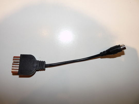
Funny enough, at the time of writing this, eBay has an auction with someone selling it right now.
After my first motivating steps into soldering, I decided to make my own cable. As always, I share some helpful info, including my mistakes as they might be helpful too and make you feel less dumb if you screw something up…
Getting the parts
Getting the right parts was trickier than I thought, mostly because I lack experience in where to get them or who to ask about them. I always get very good help from the members of the Forum64 – a great resource of knowledge and great people.
Killing a datasette. Or two.
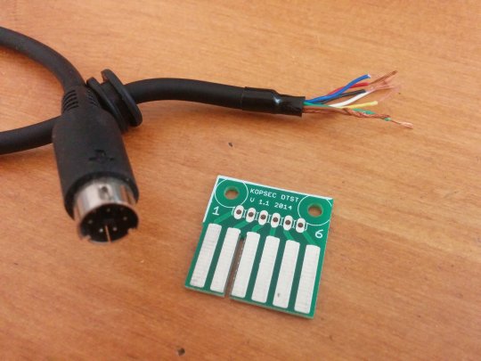
If you have an old 1531 datasette that doesn’t work anymore or you are willing to sacrifice it, you have a great start as the round connector and the wires are all there already. Just open the case of the recorder and plug out the cable. Otherwise you would need to get the DIN 7 PIN FEMALE connector from somewhere else.
The little tape port board is available on eBay if you search for a seller named “Kopsec”. He’s selling them fast and for cheap and seems to be a nice guy, so what’s not to like.
Now you should have something similar to this:
The Circuit Plan
Connecting the wires to the board isn’t hard, even for novices. This is my second soldering job (really, as anybody can see in the pictures below) and it got me no headache at all. First of all we need a so called PINOUT map for both ends of the cable. I made a nice graphic for you guys (click to enlarge):
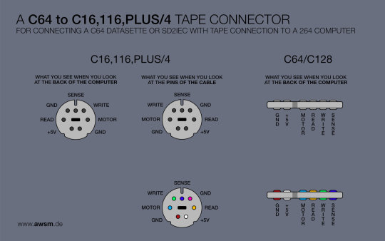
Most pinouts you can find on the net show the setup when looking at the port at the back of the computer (as seen on the left). This is fine especially if you need to solder your own cable and don’t have the datasette cable to start with.
I learned the hard way that I need to mirror all pins, because I’m looking at the cable, not at the computer port! Sounds pretty dumb, but many experts may confirm that this still happens to them from time to time. Humans. So weak.
Making the connection
So basically, all you need to do is: connect the wires from the round port to the soldering points with the same name, e.g. connect “GND to GND, +5V to +5V” etc. Some hints:
If you just want to connect a SD2IEC device, you only need to connect GND (red) and +5V (white). The other connections can be ignored.
The round port has two GND pins. You can either just ignore one GND pin or connect it to the same place as the other GND. There shouldn’t be a difference (attention, this is info I just read on the interwebz – I have no knowledge to confirm this, so don’t blame me if something goes wrong).
Free butt kicks from the gentlemen at Commodore!
Remember when I ranted that Commodore wanted to make your life miserable by using all round ports all of a sudden for the 264 series? Well, they went all the way and used cable colors that are completely unreliable. Therefore you can’t tell for sure if the red cable is GND or the white cable or any other cable. You just need to find out.
But don’t try to open the cable! By the time you have a solid idea about what wire is for what all you have left from your cable is a complete, unfixable, glued mess. The solution to the problem is a multimeter, which you can buy for cheap (mine cost about 9 Euro) at an electronics store. Watch a tutorial to find out how it works. It’s pretty easy (hold one pin to a cable on one side, the other pin to a cable on the other side and see if the display shows something).
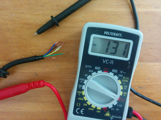
As you can see in the pictures below, my GND was red and the +5V was white. But don’t rely on it being the same for you.
Now you just need to solder everything together. I’m not giving a tutorial on how to solder, that would probably just kill innocent people. Here’s a pic of my soldering station (again, pretty cheap, around 40 Euro):
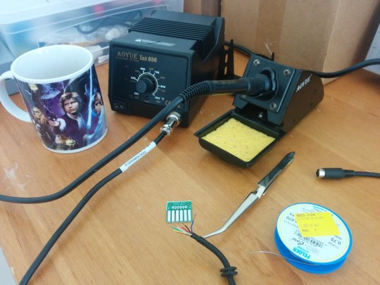
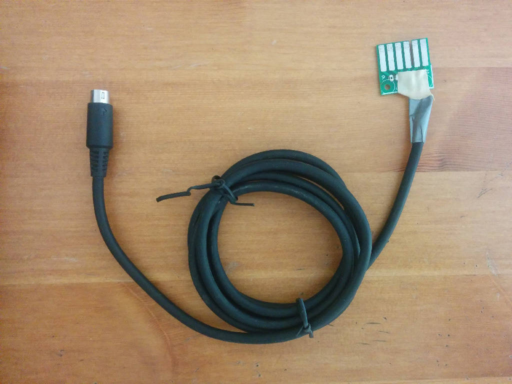
Also, a fantastic Star Wars coffee mug. After connecting all the wires, one end of the cable should look like this:
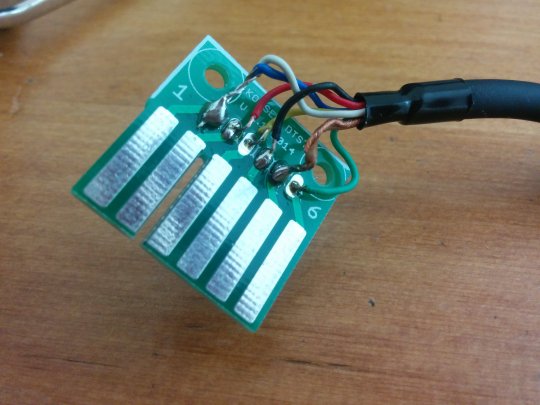
I was so proud of myself after I was done, only to realize that I made the most obvious mistake of all and soldered all the wires mirrored (see above). It took me a while to find out the reason why it wasn’t working and by that time I was running out of time, so I only connected the GND and +5V again.
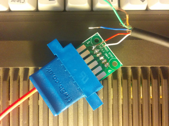
The finished cable
Some final wire cutting and we’re already done (it might take you shorter to build the cable than it took me to write this all down)!
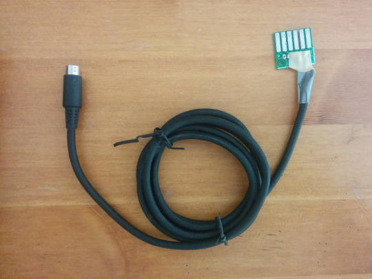
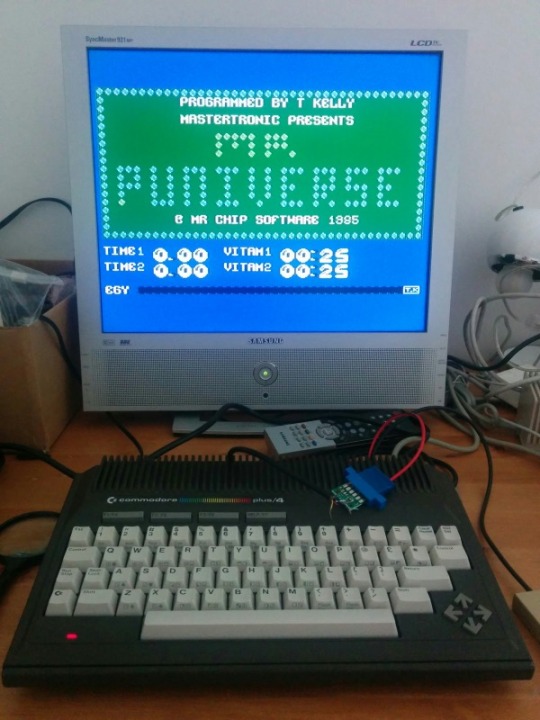
It works as expected and now I can use my SD2IEC to connect with my plus/4 (e.g. to play the marvelous Mr. Puniverse)
